How to Accelerate the Development of Electric Motor Drive Controls
By Dr.-Ing. Christoph Hahn, Head of Technical Marketing, Speedgoat GmbH
Designing electric motor controls and testing embedded controllers for motor drives is time-consuming, and tests with rotating components and under high-voltage conditions are potentially dangerous. Testing intelligently using digital twins allows for a safe testing environment that not only prevents equipment damage but also personal injury. Furthermore, it provides a continuous workflow across all test phases within a single platform. Development thus becomes faster and more innovative, and errors can be detected early on.
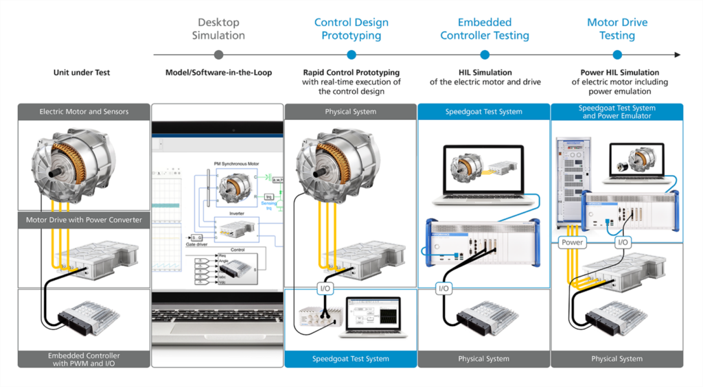
Developing controllers for electrical drives using model-based design typically begins on the desktop, followed by prototyping control designs: Rapid control prototyping allows the real-time execution of the control design on flexible and performant hardware. Once the control designs is deployed to an embedded controller, it can be tested at the signal level in a hardware-in-the-loop (HIL) setup with the electric motor and drive. And finally, the motor drive gets tested at actual power levels as part of Power HIL testing.
Desktop simulation
An intelligent model-based design approach allows to quickly try out new ideas and speed up the development process while exposing design problems early on. A seamless transition from early design and simulation on the desktop to rapid control prototyping and HIL testing is vital. An intelligent approach eliminates the dependencies of lengthy testing of the embedded platform by combining hardware, firmware, and software development into the model-based design workflow. Development and test engineers can maintain a clean system architecture and automate all steps, from deployment to testing and ensuring requirement compliance. They can continuously test and iterate the control designs at any stage of the development process.
Speedgoat test system as a controller for prototyping
In the next testing phase, a real-time test system can function as a controller for prototyping: The control design is run on the test system and validated by controlling the actual electric motor, thus testing, tuning, and optimizing control algorithms before deploying them to the final embedded controller.
Traditional prototyping is time-consuming because of the lenghty iteration cycles. The innovation speed is low, and engineers may get stuck in lengthy iterative processes. It can also easily lead to faults and hard-to-detect errors.
Rapid control prototyping with a powerful and flexible prototype controller resolves these problems. It
helps to increase the controls’ development speed considerably.
Continuously test and iteratively change Simulink control designs using hardware early in the development. Engineers can focus on innovation and experiment without the constraints of an embedded controller. This workflow helps to assure quality control and optimal control strategies for the predefined requirements. Also, automated code generation produces higher-quality code and is easier to debug. Seamless testing with a real plant connected to the real-time prototying platform effectively replaces embedded controller testing for control design validation and optimization.
To profit fully from these advantages, the test systems have to meet specific requirements: Speedgoat test systems, for instance, can be configured with performant, multi-core processors and FPGAs. Control designs for power electronics using silicon-carbide (SiC) or gallium-nitride (GaN) semiconductors can also be deployed onto Simulink-programmable FPGAs. Further, Speedgoat test systems provide turnkey I/O connectivity and communication protocol support.
Speedgoat test system for controller HIL testing
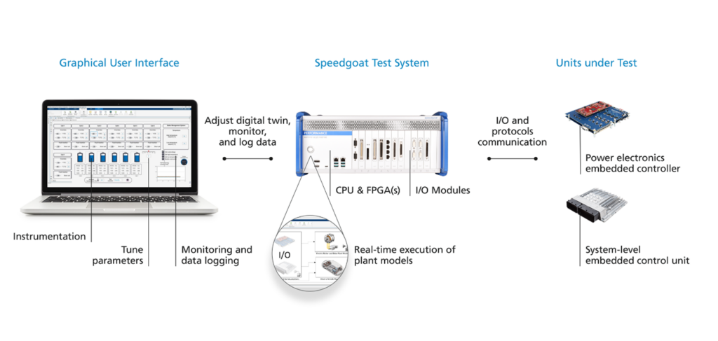
In the following embedded controller testing phase, the real-time digital twin of the motor and drive is being run on a real-time test system connected to the embedded controller. Controller-hardware-in-the-loop (C-HIL) testing allows the validation of embedded controllers for motor drives featuring field-oriented or direct torque control, allowing full test coverage, including all interfaces. Real-time simulations of power converters or motor drives can be run to validate embedded controllers with very high switching frequencies.
Controller hardware-in-the-loop (HIL) testing enables requirements-based testing of the embedded controller. Instead of the actual physical plant or motor drive, a digital twin is used for testing as it’s easier to test safely under normal as well as fault conditions. This is not possible using a traditional testing approach with a real plant – testing edge cases might damage the physical motor drive or electrical system. Also, the same testing setup cannot be recreated in a repeatable way, and the plant is not always available to test. It’s expensive to recreate and operate under all testing conditions and difficult to ensure the quality of controller testing. Traditional testing also means that control algorithm iteration takes longer, leading to low innovation speed.
Testing with a digital twin of the plant is favorable to the traditional approach: It makes it possible to define test cases for every requirement and automate testing with reproducible test conditions. Bugs can be detected early. Controller HIL testing also allows to test nominal and edge cases safely. With the high availability, it’s possible to test 24/7 continuously and to run literally millions of tests at a fraction of testing costs. As the environment from requirements to certification stays the same, it ensures the quality of controller testing. Controller HIL Testing also allows to update control algorithms and drive innovation seamlessly.
Speedgoat test systems, for example, provide turnkey I/O connectivity and communication protocol support and allow bus network simulation for HIL testing. Emulating sensors like encoders, resolvers, RTDs, thermocouples, relays, or battery cells is possible using dedicated I/O modules.
Testing electrical equipment – connected and fully powered – using a Speedgoat test system
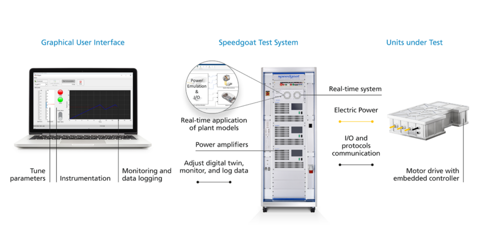
Electrical engineers use the final testing phase, power hardware-in-the-loop (Power HIL) testing, to test electrical equipment that is connected and fully powered: The real-time digital twin of the electric motor is run on a test system connected to the motor drive and power amplifier and the controller using default I/O. This allows the testing and thorough validation and verification of the motor drive at full power and, therefore, to test motor drives, power converters, and electric motors under typical operating and fault conditions before the final deployment.
Test systems enable emulating high-bandwidth electrical interfaces using power amplifiers ranging from a few hundred watts to megawatts. Power HIL testing requires the digital twin to match the electric power of the equipment precisely. Simulink and its products, for instance, allow creating high-fidelity models of electric motors, including nonlinear characteristics, experimental data, or FEA data from software like ANSYS Maxwell and JMAG-RT. With a Speedgoat test system, you can also emulate sensors like encoders, resolvers, RTDs, thermocouples, or relays.
A test system to improve the way you test
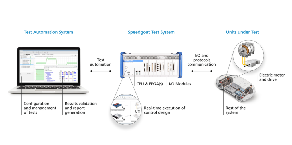
Speedgoat test systems, Simulink, and its products facilitate requirements-based testing and test automation. Using a single platform like Simulink for development and testing is vital to test efficiently. The same workflows can be used for rapid control prototyping and as plant models for hardware-in-the-loop (HIL) validation of the embedded controller or Power-HIL testing. Speedgoat test systems allow this seamless Simulink workflow integration with Simulink Real-Time. They offer off-the-shelf I/O connectivity, protocol support, and sensor emulation and are turnkey available. Application-specific models of control designs and available plant simulations accelerate the ramp-up significantly. Also, third-party calibration tools and power amplifiers can be integrated.
Conclusion
Testing the electric motor hardware – including sensor, drives and power converters – connected to the embedded controller via real I/O is crucial to developing electric motor controls. An intelligent test system for all testing steps enables continuous workflows and the safe validation of the components under normal as well as fault conditions. By testing all stages from the same environment, you develop optimal controls, assure quality, all while remaining innovative.
About the Author:

About Speedgoat:

At Speedgoat, we specialize in state-of-the-art real-time systems for real-time testing using Simulink® and Simulink Real-Time™, the real-time operating system from MathWorks. Together, our solutions allow our customers to continuously verify and validate their designs along a complete Model-Based Design workflow, including requirements specification, simulation, rapid control prototyping, hardware-in-the-loop (HIL) simulation, and deployment. Speedgoat was incorporated in early 2007 by former MathWorks employees and is headquartered in Bern, Switzerland. For more info, see www.speedgoat.com.